GOLFMK8
GOLFMK7
GOLFMK6
GOLFMKV

Cuzoe's 2015 Golf TDI S Journal

Cuzoe

Autocross Champion
Location
Los Angeles
This post is for @Drewpul, regarding soundaktor retrofit.

You need 3 parts (plus hardware), and to do some wiring...

Speaker - 4H0 907 601 D (Item 1)
I would also try to get this with pigtail... https://www.ebay.com/itm/155594876308
Module - 5G0907159 (Item 2)
You can also get xxx159B, 159C, 159D. I would just find one with the pigtail to make your life easier.
You may have better luck finding 8K0907159 in the US, these will will work as well.

Bracket - 5G0906468A (Item 3)
Picked up new, less than $20 from the dealer.

I picked up all new hardware...
2x N01508210 (Item 4)
1x N10653201 (Item 5)
2x N10335206 (Item 6)

1692203961831.png


Different view, item 2/3 here...
1692200621072.png


Power from cabin fuse panel, fuse SC34 (there will be other things wired to this, but you can tap in at TIUL T17m (brown connector), left kick panel.
Ground from wherever there's a ground... easy one is the stud just aft of the battery... your wiring is going to be routed past that location anyway.
And you need powertrain can bus, which you can also get from TIUL T17m (brown connector), left kick panel.
Then two wires from the module jump straight over to the speaker.
1692204258201.png


You will have to flash custom firmware to the module. Factory un-modified firmware has VIN/engine type lockouts. I can, at some point give some pointers on how to flash with ODIS, but that can info can be found elsewhere. Anyway... here's a thread by @Chillout on the modified firmware (big, gigantic credit to him for the work making this possible, buy him a coffee).

I have retrofitted driving modes (FPA) to my car, but for simplicity lets assume a car with no driving modes. You will want to load one of the "No-FPA" firmware versions. I am currently running the firmware from the Audi RS4/RS5... it sounds awesome. But as mentioned I have driving modes so I can set the Soundaktor to Off, Comfort/Eco, Normal or Sport. The "No-FPA" version will default to Sport mode which may be a bit much on daily basis. You'll have to try a few until you find something you like. Recently Chillout has modified some Porsche Cayenne firmware, which I will be trying soon 😬.
 

Cuzoe

Autocross Champion
Location
Los Angeles
Don't really know where to put this as it's really only in planning right now... but I figure @xabhax, @Nuje, @bobloblawGTI, and maybe even @2018gti may be interested in wasting some money, haha...

Let's talk about heated windscreens!!! Two part numbers for heated Golf glass with "facelift" style Driver Assist, so 3Q0 camera.
(I originally posted this on Ross-Tech forums but there's more traffic round these parts)

This one that is available in the states and elsewhere, seems to be an e-Golf part number, and parts.vw.com describes it as a rear windshield, haha.
Heated with Driver Assist (facelift, 3Q0 camera) - 5GE845011E NVB (credit to @xabhax for finding this PN)
https://fznparts.nl/product/vw-e-golf-facelift-voorruit-met-regensensor-5ge845011e/Don't know how long this link will be alive but the glass is pictured.

This one that is not available in the states, looks like the same glass but not an e-Golf part number
Heated with Driver Assist (facelift, 3Q0 camera) - 5G0845011 AR
https://recambiopl.com/en/code_product/5p0845011an/Again, don't know how long this link will be alive but the glass is pictured, you can see a connector at the bottom left of the pic (lower right of the windshield).

So I guess we can start with the electrical...
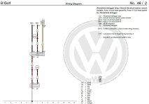
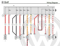
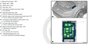
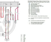
  • J47 is the Windshield Defogger Relay, which will need to be installed (position R11 engine fuse box, per the diagram), PN 4H0951253A (standard "645" 40A relay)
    • On my car there is nothing in the fuse box section where this relay goes (see below). And the relay holder has a spot for both a 646 "sized" relay and the larger square relay. Some gassers may already have the relay holder here, with a square type relay.
    • A 646 relay, which will fit in the other spot, is only rated at 25A so you should NOT use that smaller spot for your relay.
    • Recommend instead using another relay holder (part number in the section below) and just having the right relay, but in the "wrong" spot. A relay is not a current limiting device. If used as such, the relay quite quickly becomes a fire hazard.
    • Terminal 121 is 0.5mm (20 AWG) wire, tied to the output of Fuse SB17
      • This is a 7.5A fuse and will exist in your car, feeds several other things
      • It will not be replaced, as it just provides power to the relay J47 relay coil
    • Terminal 122 is 0.5mm (20 AWG) wire, goes into the cabin, BCM Plug B Pin 26
      • This is a ground for the relay coil, provided by the BCM (control via Infotainment screen)
      • Note the diagram in prior post shows BCM Plug A which is incorrect, BCM Plug B has 46 pins (Plug A and C have 73)
      • This is where your long coding will come in pre-facelift, or adaptation on facelift BCM
    • Terminal 123 is a 4mm (12 AWG) wire that is fed by Fuse SB14
      • SB 14 is a 40A fuse, which your car will not have so wiring needs to be added for the line and load side
        • This is "low profile maxi" type, although I suspect that's not the official name it'll get you what you want, haha.
        • Line side of this comes straight off the battery bus bar tied to (large, threaded) terminal 508 at the front of the box
        • Load side is a 4mm (12 AWG) wire which jumps right over Terminal 123 of the J47 - Windshield Defogger Relay
    • Terminal 125 is a 4mm (12 AWG) wire that is spliced (into two 4mm (12 AWG) wires) that go to connectors left/right windshield base
      • The diagram is sort of weird, and shows Z2 - Windshield Defogger, which I believe is the element of the windshield
      • So this Z2 has a connection on the left and right side (base) of the windshield
      • The schematic calls them A1 and B1 though it doesn't say which side is right/left (and it doesn't matter)
      • Not shown in my diagram for the Golf R but Tiguan drawing shows these, 1 wire connectors, both PN 071973851
        • And the repair wire with pin for this connector 000979307E, not found for less than $30-40 yet :cautious:
        • For what it's worth, eBay 071973851 pigtails are $19/ea so... yea.
      • Diagram shows "C1" which I suspect as the front windshield chassis ground
      • Clips to hold harness near base of windshield... 3C1971303 and 3C2971303
Windshield Defogger 1.JPGWindshield Defogger 2.JPGWindshield Defogger 3.JPGWindshield Defogger 4.JPG


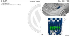
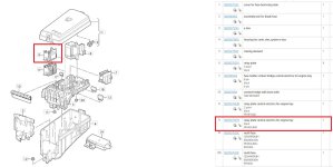
Now for the fuse panel, in my car there nothing in this second row, so an insert is required...
  • This will be position R11 of the engine fuse box (Fuse Panel B for you purists).
  • There are two inserts that can go in this spot, shown as item 6 and 9 of the picture.
  • You want item 9, PN 5Q0937507B which has a space for R11 (that we need)
    • Keen eyes may note that item 9 is for PR Code 4GW which is... heated insulating windshield!
    • This PR Code is shown in one place on the Golf drawing, but is all over the Tiguan drawings
    • One Shot.JPG
  • You may find you already have this insert there, with position R8 used... circle gets the square!
    • Note, I am only talking Golfs here, Tiguan is a little different with the fuse layout.
Fuse Panel Pic.JPGFuse Panel Parts.JPG

Hopefully someone with more patience (and resources) than I will find the repair wire part numbers for these relays. In a shamefully delayed moment of insight I picked up a spare fuse panel.
All that means is I have plenty of wires with the the terminal types needed for fuses. Some repair wires can be $30-40 alone. I paid under $50 shipped for the spare fuse panel.
https://golfmk7.com/forums/index.ph...home-for-your-mkvii-today.329302/post-7980691
 
Last edited:

2018gti

Drag Racing Champion
Location
Massachusetts, USA
Car(s)
Golf GTI Autobahn MT
Great research! I would for sure try this if my windshield had to be replaced. But at the same time, the Webasto does a pretty good job at defrosting. Always the question of whether to cram another retrofit into my car 😂

It really does seem to be just the windshield, the relay, and wiring.. hmm
 

Cuzoe

Autocross Champion
Location
Los Angeles
Great research! I would for sure try this if my windshield had to be replaced. But at the same time, the Webasto does a pretty good job at defrosting. Always the question of whether to cram another retrofit into my car 😂

It really does seem to be just the windshield, the relay, and wiring.. hmm
Yea, had the research been done/shared before my DAP retrofit windshield been installed I would have done it at the same time. And even now I wouldn't be doing it except that I have a chip right in front of my face that requires the windshield be replaced.

I garage park, in Socal so don't need this windshield or websasto. But man alive websasto would be cool... or, hot. My TDI, according to build sheet, has the aux heater (PTC) to warm the cabin anyway. It was coded accordingly from factory (single bit in 08 - HVAC) although I've never physically confirmed it's there.
 

Cuzoe

Autocross Champion
Location
Los Angeles
This update is for myself (mostly) so that I have a record of what I installed and how I configured for my RGB lighting. It likely won't make sense unless you've already spent (too much) time reading my RGB ramblings in other places... mostly here though.

As secondary and tertiary matters... I want to be able to explain, if asked, what I did in case anyone else is interested. I also have an OCD-adjacent goal to clean up the adaptations in my BCM. Right now I have a lot of (RGB lighting) related channels set to active though they need not be... and I don't like that.

Anyway... on to the fun stuff yea?

Light GroupRGB LED Part NumberInstall Location (in my car)Function AssignmentVerbauinfo_HMI (sun icon)Alt functions I've tested.
018W0 947 355 KMiddle Console AreaCenter consoleHMI_1 00010000Door, Instrument, Speaker
048W0 947 355 JNot installed yet (dash strip likely)N/AN/ADoor, Instrument, Console
078W0 947 355 CFront Door StripDoorHMI_2 00010000Instrument, Console
088W0 919 390 BFront/Rear Door PocketsDoorHMI_2 01000000Instrument, Console
098W0 947 355 ENot InstalledN/AN/ADoor, Roof
108W0 947 355 FNot InstalledN/AN/ADoor, Roof
128W0 947 355 GFront Door HandlesDoorHMI_2 00000100
128W0 947 093Front Door Handle (hold)DoorHMI_2 00000100Console
128W0 947 094Front Door Handle (hold)DoorHMI_2 00000100Console
13 & 14​
8W0 947 415 (A - D)FootwellsFootwellHMI_1 00000100

First note, this is just how I've installed RGB LEDs in my car, and their groups. This is not an exhaustive table for what LEDs belong to which group, or the functions a given group can be assigned. In researching this whole RGB LED thing I kept finding "mismatches" in the coding. Well, it turns out that some RGB LEDs can be assigned to different groups depending on the function. And some RGB LEDs seem to have a hard group assignment. And in most cases a given group, although it can be assigned any function, will not actually work for all functions.

Another note, about why I "grouped" Group 13 and 14... RGB footwells requires coding that does not make sense to me, but is required for them to work. Not included in the table is a channel named "verbauinfo_gruppe_x" which in most cases is set to "multicolor." For whatever reason, verbauinfo_gruppe_13 must be set to "single color" and verbauinfo_gruppe_14 gets set to to "NOT-DEFINED" otherwise RGB footwells will not work.

More to come, probably.

At the front door disconnects I chose 3 pins on the end of the first row for the RGB Lights, pick any 3 empty ones you want though...
Pin 15 - Power
Pin 16 - Ground
Pin 17 - LIN Bus

At the rear door disconnects I had some "complications" because I've also added illuminated KESSY rear door handles. This mean I only had one spare pin, which had to be for the LIN bus. I picked up 12V (Terminal 30) and Ground inside the door. This turned out to be a non-issue. In looking at the wiring diagrams I mistakenly though I only had one spare pin, but I have 3... perfect. The two "additional" that I found are available because I do NOT have Fender.
Pin 6 - Power - Inside Door, from disconnect Pin 2 (or window regulator motor pin 2)
Pin 7 - Ground - Inside door, from disconnect Pin 1 (or window regulator motor pin 1)
Pin 15 - LIN Bus
 
Last edited:

Cuzoe

Autocross Champion
Location
Los Angeles
Got the driver done, it looks great in person, although I (my phone) can't seem to capture a good picture that doesn't make at least one of the lights look too bright or strangely colored...


Anyway, lets talk about things that won't matter to most people, yea?

The ambient lighting depiction on the MIB looks like this...
- lots of light in the pocket
- no light in the door open handle (this will be fixed soon-ish, MIB graphic editing)
- ignore the cupholder strip... I have ambient lights there but currently just a placeholder graphic
Depiction.png


Well, all of the guides I've seen for the Golf install the pocket light facing down, below the arm rest area...
- Ignore the messy car, I'm busy with some things
- For you eagle eyed folks, ignore that missing engine start button, I'm also retrofitting KESSY
The usual spot.png


I don't really like this position for a few reasons. The first is that I can see that light from my driving position if I don't have a passenger. The second, and more annoying to me, is that it doesn't illuminate the front of the pocket at all. Not only does this not match the MIB depiction, but in practice the light is kind of useless. I don't keep anything in the "rear" of the pocket that I need to see. That's hard to get to when seated anyway.

So for the drive side I installed the light on the rear vertical of the pocket...
- It's very obvious when the door is open, but you can't see it with door closed, even from the passenger side with no driver.
- But now the entire pocket is illuminated, which matches the depiction and is more functional... lets call that doubleplusgood?
- My passenger side does not have the grab handle light so I've gotta pull that door card again anyway, at which point I'll also move the pocket light.
The other spot.png
 

Drewpul

New member
Location
Glen Ellyn, IL
Car(s)
Golf Sportwagen TDI
Cuzoe,

Time to do the rear brakes on my tdi sportwagen. I'm considering upgrading from 253mm to 272mm.

I've followed a few threads and haven't come across the answer...but I assume I need a larger caliper, dust shield? And I think elsewhere you posted that you would need a longer brake line?

I know you have since upgraded to the R setup with the e parking brake. I'm not looking to go that advanced :LOL:

Also, love teh yellow calipers. Planning on painting or powder coating mine yellow too. I think they'll pop nicely against my silk blue. Did you paint them youself? If so, what paint/color did you use?
 

Cuzoe

Autocross Champion
Location
Los Angeles
I initially went to 310mm brakes from the GTI PP. This did require different brake lines. I'm not sure if you will need lines going to 272mm. You are correct regarding the caliper/bracket. Dust shields will be close. I flattened the edges of mine with some flat nose pliers instead of replacing them, when I went to the 310mm PP brakes. I'm not sure which part number shields will fit. But IIRC removing them required some additional work (like maybe the are mounted with bearing assemblies, or something like that. For sure more work than the fronts).

Later when I did the R brakes I had to trim some areas to fit the e-brake motor. Just used some standard home depot tin snips then hit the rough/sharp edges with a sanding drum on a Dremel.

It's G2 "Porsche Speed Yellow" paint... https://g2usa.com/products/porsche-l12g-brake-caliper-paint
I had it sprayed, done off the car on new calipers.
 
Top